v0.3.0 of lirc_web has just been published to npm.
This release targets mobile optimizations and performance. lirc_web now behaves more like a native app when added to the home screen of a mobile device. A favicon is now shown on the home screen, the URL bar will be hidden from view, and lirc_web will be selectable from the device’s multitasking screen. Furthermore, CSS assets are bundled into a single request, small images are now base64 encoded, and an application cache has been introduced to cache all assets locally between requests.
In my testing, with a warm cache, lirc_web now fires a load event within 300ms.
Here’s the relevant piece of CHANGELOG.md that describes all updates since v0.2.0:
1234567891011121314151617181920212223242526272829
## [0.3.0] - 2016-03-13

* Adds `grunt-contrib-cssmin` task to combine all CSS requests into one
* Adds ability to set lirc socket in `config.json` (thanks @pmgration)
* Base64 `left-arrow.png` image to reduce a request
* Adds application cache manifest file for offline caching

## [0.2.4] - 2016-01-13

* Extracts macros into a standalone lib/macros.js file
* Adds Favicon (thanks @flochtililoch)
* Adds npm run test:watch action (thanks @OvisMaximus)
* Travis build will now run linter
* Updated dependencies
* Uses local version of jQuery for testing now

## [0.2.3] - 2016-01-03

* Fixing bug where labels were loaded before config (thanks @flochtililoch)

## [0.2.2] - 2016-01-01

* Removing `Makefile` for running tests. Only need `package.json`.
* Fixing .gitignore error for the global lirc_web build

## [0.2.1] - 2015-12-31

* `lirc_web` can now be installed globally and called by `lirc_web` from CLI
* Adding ESLint to the mix and ensuring all JS conforms to Airbnb ES5 standards
The lirc_web project (available at https://github.com/alexbain/lirc_web) has been updated to v0.2.0, which contains some new features and bugfixes. Here’s the summary of the new functionality now available in the project:
123456789101112131415
[0.2.0] - 2015-12-30

Adding blacklist configuration option to hide unused keys from UI (thanks @OvisMaximus)
Adding support for SSL (thanks @de-live-gdev)
Fixing example config in the README (thanks @de-live-gdev)
Fixes url escaping bug with macros and remotes (issue #23)

[0.1.0] - 2015-12-30

Locking npm versions to ensure future install work
Adding CHANGELOG.md
Adding /refresh link on bottom to reload UI after making changes to LIRC (thanks @f00f)
Adding ability to set custom labels on command and remote names (thanks @elysion)
Adding Apple mobile app capability, disabling zoom (thanks @elysion)
Moving Lato fonts locally to remove external network dependency
On a related note, lirc_node (available at https://github.com/alexbain/lirc_node) has been updated to v0.0.4. There’s no new functionality in this release, simply locked NPM dependency versions and the addition of a change log.
If you run into any issues with either project, let me know in the comments or (ideally) via the issues page.
In this post, I’m going to cover writing a short script that automatically reconnects a RaspberryPi to a WiFi network. The script will check to see if the Pi has network connectivity and, if it’s offline, will restart the wireless interface to bring it back online. We’ll use cron to schedule the execution of this script at a regular interval.
There are a few ways to determine if the RaspberryPi has network connectivity. For this script, we’ll be using ping.
Writing the script
To get started, we’ll need to determine if the RaspberryPi is connected to the network. To do this, we’ll attempt to ping a server and see if we get a response. If the command succeeds (RaspberryPi receives a response from the server), we have network connectivity. If the command fails, we’ll turn wlan0 off and back on.
123456789101112131415
#!/bin/bash

# The IP for the server you wish to ping (8.8.8.8 is a public Google DNS server)
SERVER=8.8.8.8

# Only send two pings, sending output to /dev/null
ping -c2 ${SERVER} > /dev/null

# If the return code from ping ($?) is not 0 (meaning there was an error)
if [ $? != 0 ]
then
    # Restart the wireless interface
    ifdown --force wlan0
    ifup wlan0
fi
Name the script something memorable (wifi_rebooter.sh), and place this script in /usr/local/bin. Make sure it’s executable by running:
1
chmod +x /usr/local/bin/wifi_rebooter.sh
Scheduling regular execution
To ensure the script runs automatically, we’ll use cron. The frequency that you run this script is a matter of personal preference - I chose to run the script every five minutes.
To schedule the script, open /etc/crontab for editing and add this line to the bottom:
1
*/5 * * * * root /usr/local/bin/wifi_rebooter.sh
This will ensure that the script is run, as root, every 5 minutes. If you’re unfamiliar with cron syntax, take a look at the cron format.
Testing
To test that the script works as expected, we are going to take down the wlan0 interface and wait for the script to bring it back up. Before taking down wlan0, you may want to adjust the interval in /etc/crontab to 1 minute. Also, note that this will immediately disconnect you from your shell session.
To take down wlan0 to confirm the script works, run:
1
ifdown --force wlan0
After waiting patiently for ~1 minute, try SSHing back into your RaspberryPi. Assuming everything worked, your RaspberryPi should have automatically reconnected to WiFi. Don’t forget to adjust the interval in /etc/crontab back to a more appropriate value, if you set it to one minute for testing.
Hopefully this helps keep your RaspberryPi projects online! If you have any questions, or have an alternative method to suggest, feel free to leave a comment.
In this post I’m going to talk about two features I’ve added to the lirc_web project. lirc_web is a NodeJS app I wrote that provides a web interface and JSON based API for controlling LIRC, an open source project that lets you control IR devices from the command line. I built lirc_web to run on a RaspberryPi along with an expansion board I designed so that anyone could build their own fully customizable universal remote that is controllable via a web interface from any web connected device (phone, tablet, laptop, smart watch, etc).
If you’d like additional context about the project, you may be interested in:
In v0.0.8 I’ve added two new features - macros and repeaters.
Macros
Macros allowing you to execute multiple IR commands in rapid succession from a single button tap or HTTP request. The use case for this would be when you need multiple devices to be turned on and set to a certain mode to perform an activity (say, playing a video game or watching a movie). An example macro might be:
Turn TV on
Set TV to input 3
Turn receiver on
Set receiver input HDMI2
Turn game console on
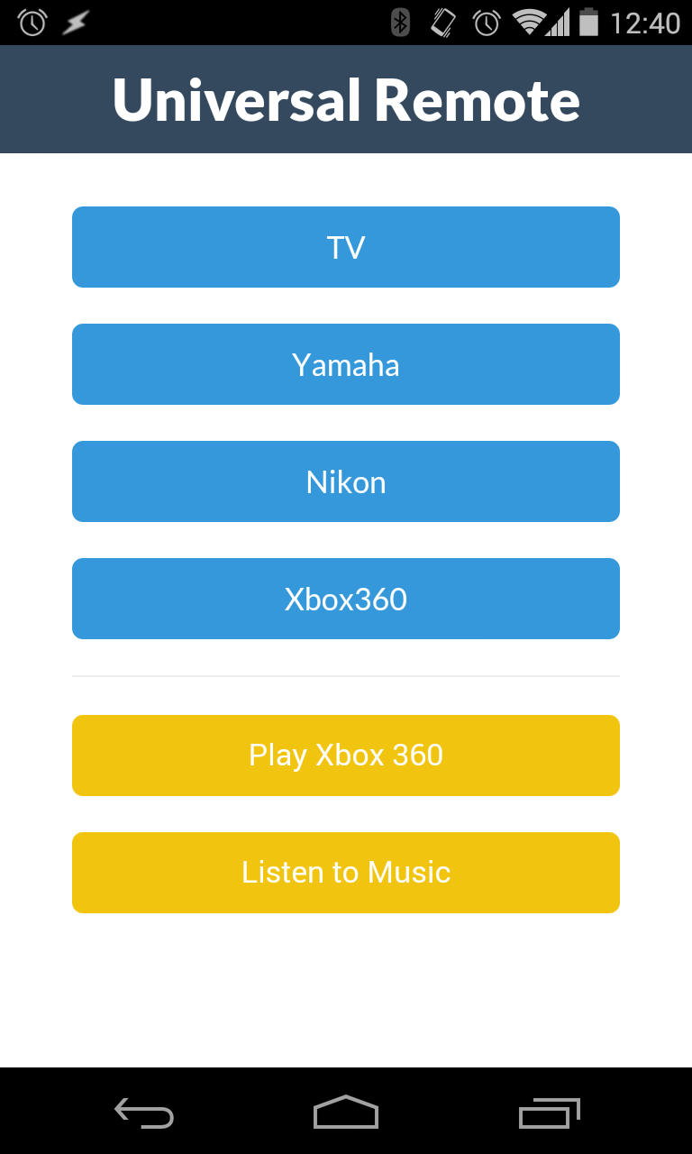
Macros make performing common multi-step tasks simpler. In addition, Macros are exposed via the API, which means you can execute macros by sending an HTTP request from a growing number of internet of things or web connected devices. For example, you could adjust the volume of the TV from your Pebble watch or change the TV channel by waving your arm while wearing a Myo armband.
Macros are defined in a JSON configuration file (config.json) that lirc_web expects to find in the root of the project. Here’s an example:
The macros key is an object of keys (labels) that are set to arrays of [remote, command] pairs. The remote and command strings should match what is defined in the LIRC configuration file. A small delay is introduced between each command to ensure they are all received.
After you create or change anything in config.json, you will have to restart lirc_web. Afterwards, you’ll see your macros listed at the bottom of the user interface.
Macros are also available via the API. You can execute them by creating a POST request to a url like so:
1
http://ip-of-remote/macros/Play%20Xbox%20360
Repeaters
Repeaters are a type of button that repeatedly send it’s command as long as it is held down. The use case for a repeater would be a volume button that should continue to change the volume as long as it’s pressed - rather than needing to tap it many times.
Repeaters are also specified in the configuration file. Here’s an example:
Similar to macros, the name of the remote and command must match the names you gave these commands in the LIRC configuration file. If you want to change the name of a button, update the LIRC configuration file and restart LIRC / lirc_web.
Enjoy
I’ve found these two features make the Open Source Universal Remote significantly more useful for common tasks. If you have any suggestions for new features or ideas on how to improve the project, please share your ideas in the comments.
Previously, I discussed how I built an open source universal remote using a RaspberryPi, an expansion board, and a NodeJS web application. This device allows me to control any infrared device in my home from my phone, smart watch, laptop, or other web connected device. I use the remote daily, and it’s sparked my curiosity to devise new ways of enhancing my environment with internet connected devices.
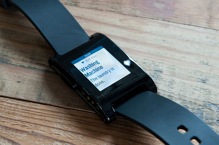
In this post, I’m going to cover a new project I recently finished - creating a device that monitors a washer or dryer and sends a text message when it detects that a load of laundry has finished. Beyond the novelty and simplicity of receiving a text message when the laundry is done, I built this device for two reasons. First, I wanted a project that introduced me to accelerometers - a sensor I’ve wanted to work with. Second, I wanted to take another stab at applying the principles of progressive enhancement, a web software concept, to the physical world.
“Progressive enhancement uses web technologies in a layered fashion that allows everyone to access the basic content and functionality of a web page, […] while also providing an enhanced version of the page to those with more advanced browser software […].” (Wikipedia)
I wanted to see if I could apply the concept of progressive enhancement to the physical world by enhancing an existing appliance (in this case, a washer or dryer) with new digital functionality - without modifying it’s existing form or interface. I wanted the appliance to look and behave exactly as it did before the modification, and I wanted no visual evidence that my device had been installed. After some brainstorming, I came up with an approach that met my goals. Read on to learn how I build it, and how you can build one yourself.
Overview
At a high level, the project works as follows: a 3D printed enclosure magnetically attaches to the outside of the washer or dryer. Inside the enclosure is an Electric Imp microcontroller and an ADXL335 accelerometer. The accelerometer measures the vibrations of the washer and dryer. The microcontroller has firmware on it that samples the accelerometer, processes the output, and periodically sends a computed result to a server in the cloud. The server receives the output and runs an algorithm that determines whether the washer or dryer is currently running. Once the server has confidently determined that the washer or dryer has finished running, it sends an SMS (using Twilio) to one or more predefined phone numbers.
I’ll cover the implementation in more detail below. This post is broken down into three sections:
The hardware
The 3D printable enclosure
The software
I’ll end with a conclusion and some closing thoughts.
Part 1: The Hardware
For this project, I purchased most of my parts from Adafruit, an online retailer of electronic components. The rest of the parts I purchased from Amazon. Here’s the bill of materials:
2 small rare earth magnets (available from any hardware store)
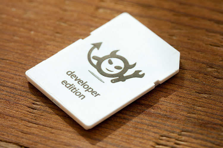
Electric Imp
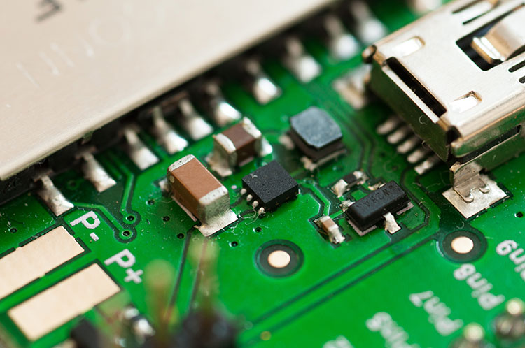
For this project, I chose to work with the Electric Imp microcontroller. The Electric Imp is a microcontroller in the form factor of an SD card with a 32bit Cortex M3 processor. What I find most interesting about the Electric Imp is that it also includes an 802.11b/g/n chip, making it one of the smallest WiFi enabled microcontrollers I’ve found. I also used the April development board, a breakout board from the Electric Imp team, which breaks out the pins on the imp and provides a mini USB connection for power. You can see that development board, a green circuit board, in the image beneath the “Hardware” header.
Configuring the Electric Imp with your WiFi credentials is done through a clever process called BlinkUp. The Imp itself contains a phototransistor, which enables you to program your WiFi credentials optically, via an app on your Android or iOS device. Once you install and configure the app, the display on your phone strobes in a pattern that the Imp recognizes, which programs the WiFi credentials into the Imp. The process only takes a few seconds, and it worked flawlessly for me the first time.
Once you’ve programmed your WiFi credentials onto the Imp, it will automatically connect to the Electric Imp cloud service. From there, you’re able to login to the web based IDE and program the imp via your web browser. The IDE handles deploying code updates to the device, as well. I’d like to see a GitHub integration, which would provide version control, so hopefully that’s on their roadmap.
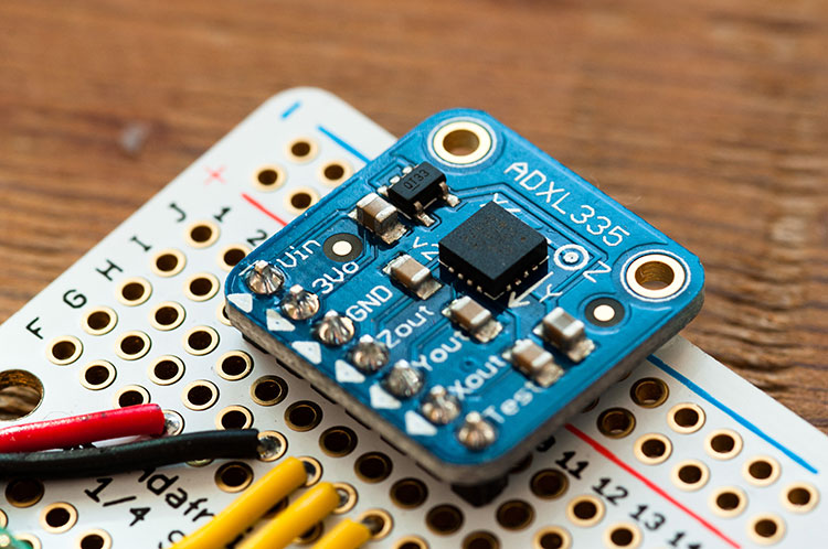
ADXL335 Analog Accelerometer
For the accelerometer (the component that measures the vibration of the washing machine / dryer), I chose the ADXL335. The ADXL335 is a 3.3V analog accelerometer sensitive to +- 3g. The device itself is widely used, and I found plenty of documentation online. In addition, Adafruit sells a breakout board (listed above in the bill of materials) that made including the device in my project an easy decision. The breakout board that Adafruit sells also allows you to connect the accelerometer to a 5V microcontroller, such as an Arduino.
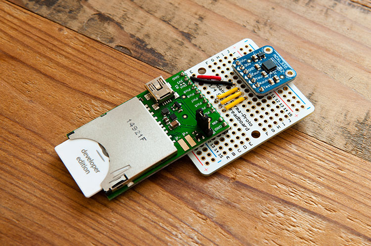
Assembling the Hardware
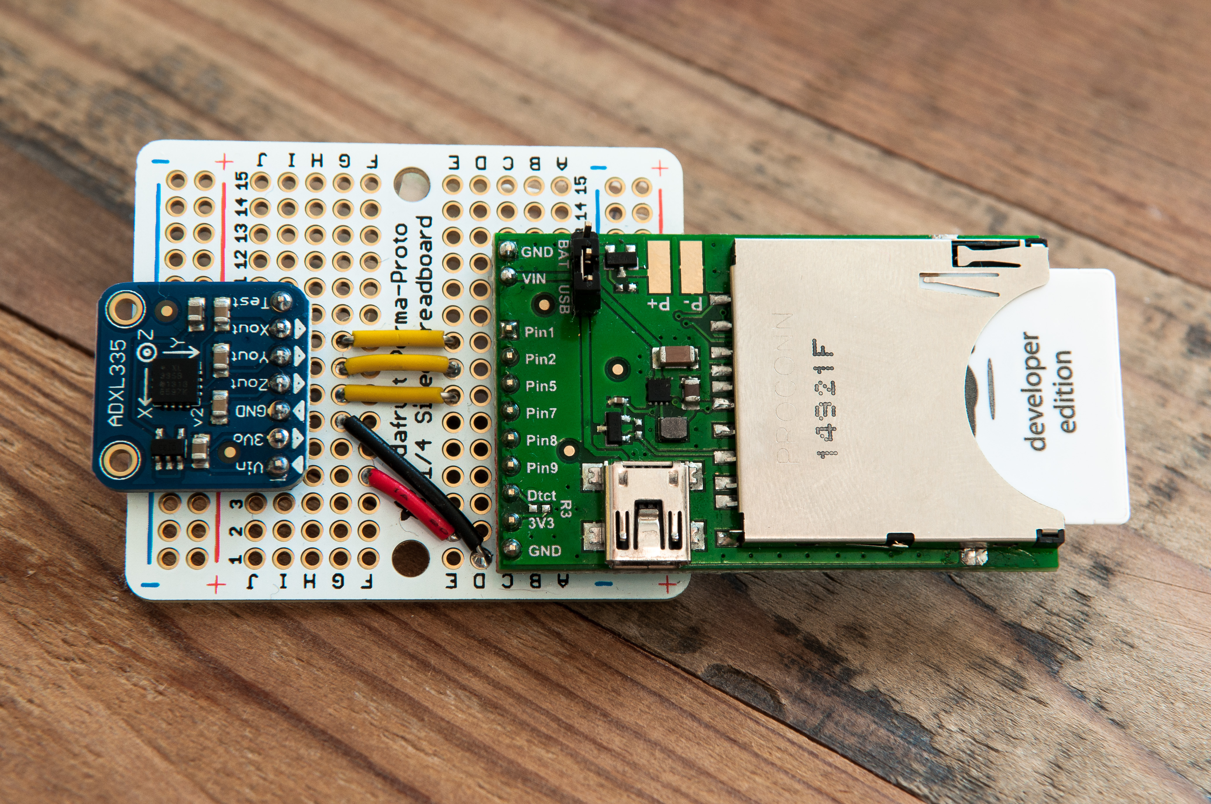
The assembly of the device is relatively straightforward. First, you will need to assemble the April development board and the ADXL335 breakout board by soldering the header pins onto the breakout boards. Next, you’ll need to solder both breakout boards into the perma-proto board. Lastly, you’ll solder in the 5 wires to enable the two components to communicate. If you intend to use the 3D printable enclosure, please ensure that the two components are mounted identically to the image above.
The picture above shows how the device looks when assembled, and here are the specifics:
Pin 1 from Electric Imp is connected to the X-out pin on accelerometer.
Pin 2 from the Electric Imp is connected to the Y-out pin on accelerometer.
Pin 5 from the Electric Imp is connected to the Z-out pin on accelerometer.
3V3 pin from Electric Imp is connected to the Vin pin on accelerometer.
GND pin from Electric Imp is connected to GND pin on accelerometer.
At this point you should be able to:
Boot the device up with a USB power supply
Program the Electric Imp to connect to your WiFi
Log into the Electric Imp web based IDE to program the device
Part 2: The 3D Printable Enclosure
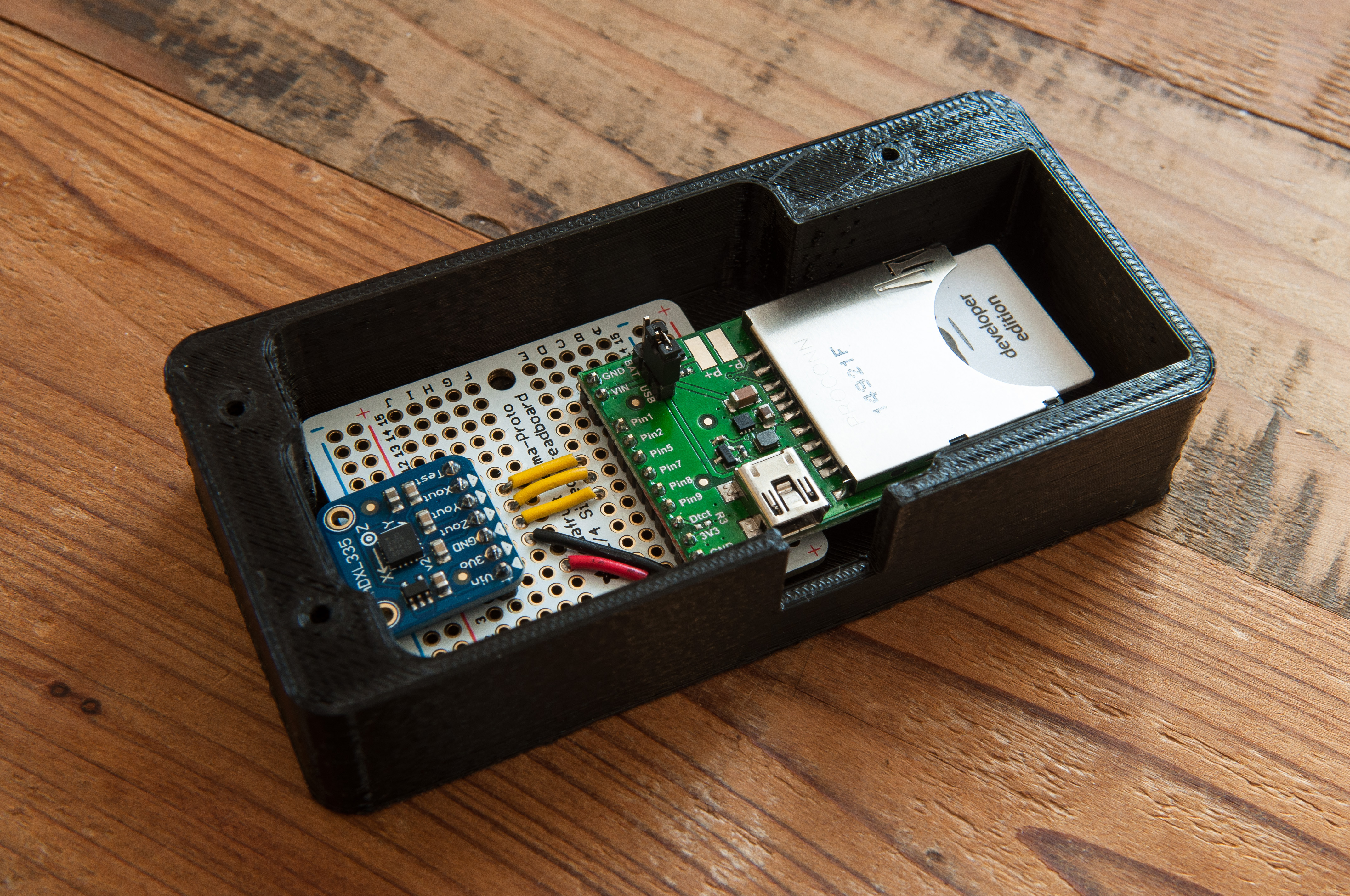
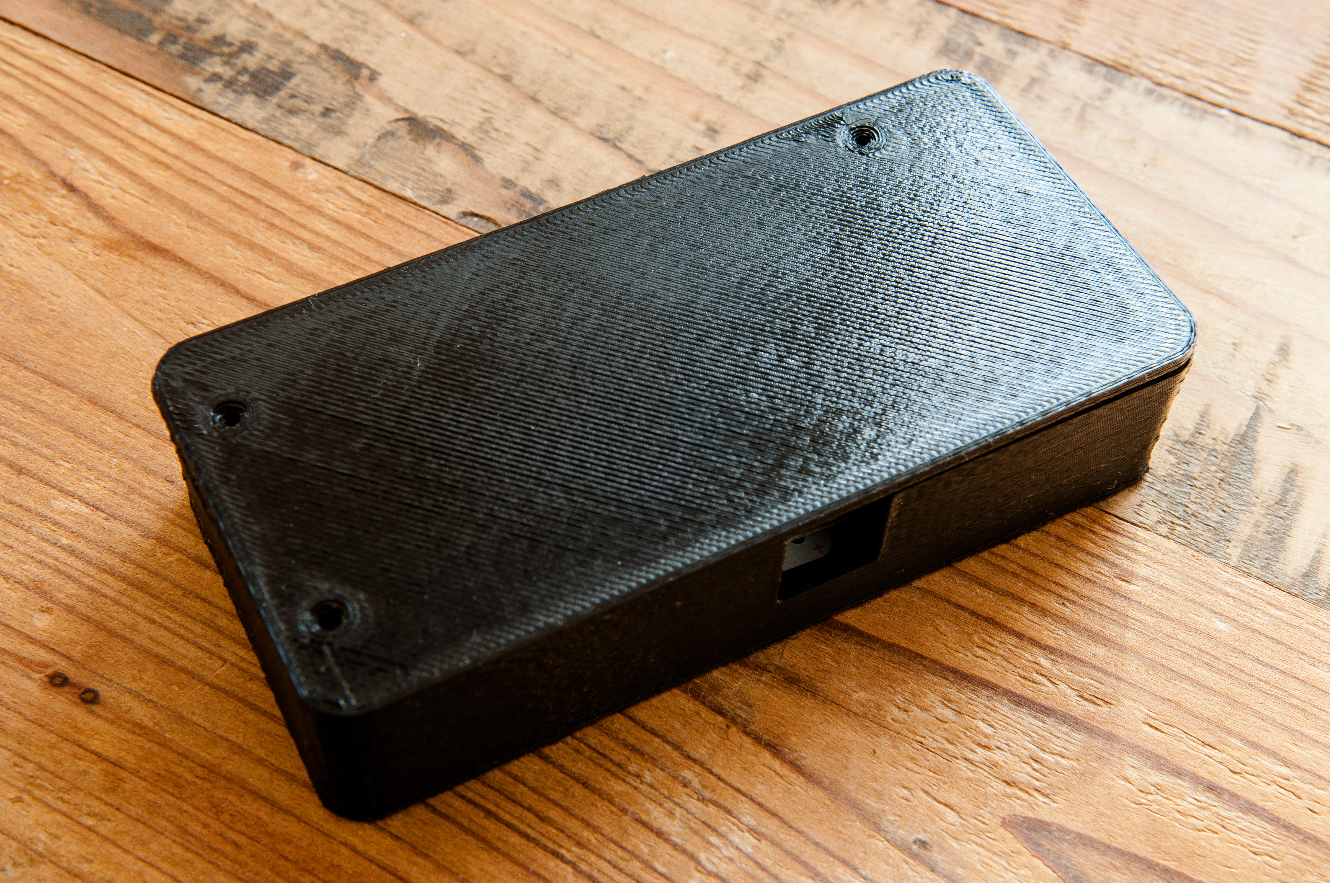
For this project, I wanted a custom enclosure that would enable the device to be sealed from dust and debris. I contacted a friend of mine, John Steenson, who agreed to help me design a 3D printable enclosure for the project. He has agreed to let me post the STL files for the case, which you can download and have 3D printed yourself. I had my case printed from a local printer that I found on the 3D Hubs service. I had a great experience with 3D Hubs, and highly suggest it if you’re trying to find a local 3D printer.
The above photos show the device mounted in the case (with and without the lid). Inside of the case, but beneath the device, I have attached (with two sided tape) the two rare earth magnets. I then placed a thin sheet of plastic between the magnets and the device to ensure there is no chance of electrical short. I have not found that the magnets interfere with the device in any way. The two magnets are what enables the device to attach to the washer or dryer.
Screws / nuts for mounting device within enclosure and securing lid:
All part numbers are from McMaster-Carr. Per my friend John, quantities noted are the quantities required for assembly, not package quantity. You’ll have some extra parts, but they’ll probably come in handy for future projects down the road.
3x - 91420A008
2x - 92000A015
2x - 93475A195
5x - 90592A004
1x - 8461K12 - Trim to fit
Part 3: Writing the Software
When writing software for the Electric Imp, you write two programs. The first program, called the “Device”, runs on the Electric Imp hardware. The second program, called the “Agent”, runs on the Electric Imp cloud. The Agent has the ability to send and receive HTTP traffic, making it a perfect candidate for the Twilio API, a RESTful API that allows you to send SMS messages.
For this project, the Device samples the accelerometer 50x a second. I found this to be frequent enough to get a clear picture for how much the washer or dryer is vibrating. For each sample, I determine the magnitude of the accelerometer vector and compute the percentage of change against the previous sample’s magnitude. I track the amount of change over 5 seconds (250 samples), and return that value to the Agent. In my testing, I found that the average reading when the machine was turned off to be between 100 and 250. When the washer or dryer are running, I find the samples vary between 275 and 6000 depending on what stage of the cycle the machine is in.
The Agent receives the total amount change over the past 250 samples, and compares that against a threshold to determine if the machine is ON or OFF. If the value is above the threshold, the device is experiencing enough vibration where it’s safe to call the machine ON. In my testing, I found 280 to be a good threshold to determine if the washer or dryer was running. Once the Agent receives N consecutive samples above the threshold, it enters the RUNNING state. Then, at some point in the future, once the Agent receives M consecutive samples below the ON threshold, it returns to the OFF state. These delays help take into account lulls in vibration during a typical laundry cycle (ex: filling the washer, rinse cycle, draining the washer). Depending on your appliances, you may need to adjust the thresholds in the Agent to reduce false positives. Finally, when returning to the OFF state, if the device was in the RUNNING state, an SMS notification is emitted (via Twilio) to each phone number stored in the phoneNumbers array.
Note: The Agent code requires you to setup a Twilio account and enter your Twilio credentials before you can send any messages. Twilio, at the time of writing this article, charges $0.01 per text message. At the rate I do laundry, it should cost < $2 a year to send these text messages.
Note2: If you would like to log all of your data to a persistent data store (either to show on a web page, or just to analyze output), Firebase is a great option, and they have a free tier. Just change logToFirebase to be true and enter your Firebase URL if you want to enable this feature.
total <- 0; // Sum of % change from all samples
n <- 0;     // Counter for number of samples read
last <- 1;  // Previous reading of magnitude

function readSensor() {
    // Time interval
    local interval = 0.02;

    // Get source voltage, should be 3.3V
    local vRef = hardware.voltage();

    // Read in ADC values from accelerometer
    local adcRx = hardware.pin1.read();
    local adcRy = hardware.pin2.read();
    local adcRz = hardware.pin5.read();
    // server.log(format("Raw ADC values: %f, %f, %f", adcRx, adcRy, adcRz));

    // Convert 16bit ADC accelerometer values (0-65535) into voltage
    local voltsRx = (adcRx * vRef) / 65535.0;
    local voltsRy = (adcRy * vRef) / 65535.0;
    local voltsRz = (adcRz * vRef) / 65535.0;
    // server.log(format("Voltages: %f, %f %f", voltsRx, voltsRy, voltsRz));

    // Subtract 0g (1.5V at 3V, 1.65V at 3.3V)
    local deltaVoltsRx = voltsRx - (vRef / 2);
    local deltaVoltsRy = voltsRy - (vRef / 2);
    local deltaVoltsRz = voltsRz - (vRef / 2);
    // server.log(format("Adjusted voltages %f, %f, %f", deltaVoltsRx, deltaVoltsRy, deltaVoltsRz));

    // Convert from voltage to g, using sensitivity of 300mV
    local rX = deltaVoltsRx / 0.3;
    local rY = deltaVoltsRy / 0.3;
    local rZ = deltaVoltsRz / 0.3;
    // server.log(format("Gs: %f, %f, %f", rX, rY, rZ));

    // Compute magnitude of force
    local magnitude = math.sqrt(math.pow(rX,2) + math.pow(rY, 2) + math.pow(rZ, 2));

    // Compute % change since last reading
    local change = math.fabs((magnitude - last)/last) * 100.0;

    // Store magnitude in last for next time
    last = magnitude;

    // Log magnitude and percent change
    // server.log(format("magnitude: %f, change amount: %f", magnitude, change));

    // Increment total with % change, increment N
    total = total + change;
    n = n + 1;

    // Log data to server once ever 250 samples (5 seconds)
    if (n >= 250) {
        agent.send("data", total);
        n = 0;
        total = 0;
    }

    // Sleep until time to read sensor again
    imp.wakeup(interval, readSensor);
}

// X input
hardware.pin1.configure(ANALOG_IN);

// Y input
hardware.pin2.configure(ANALOG_IN);

// Z input
hardware.pin5.configure(ANALOG_IN);

// Start reading the sensor
readSensor();
Here is the code for the Agent, which determines when to send an SMS
// Run on Agent

// Thresholds to adjust for better accuracy
dataThreshold <- 280; // Minimum accelerometer value to count as ON
onThreshold <- 24;    // Number of ON samples before machine enters RUNNING state
offThreshold <- 60;   // Number of OFF samples before machine enters OFF state

// State variable
running <- false;

// Keep track of counts
onCount <- 0;
offCount <- 0;

// Twilio
twilioURL <- "https://USER:PASS@api.twilio.com/2010-04-01/Accounts/ID/Messages.json";
twilioHeaders <- { "Content-Type": "application/x-www-form-urlencoded" };
twilioNumber <- "+14155551212";

// Array of phone numbers to be contacted with the laundry is done
phoneNumbers <- ["+14155555555", "+14155555556"];

// Firebase
logToFirebase <- false;
firebaseURL <- "https://FIREBASE_URL.firebaseIO.com/data.json";
firebaseHeaders <- { "Content-Type": "application/json" };

// Called every time the imp emits data
device.on("data", function(data) {

    // Is there enough accelerometer activity for the device to be considered ON?
    if (data >= dataThreshold) {
        onCount = onCount + 1;

        // Prevent overflow errors by resetting onCount when it gets close to limit
        if (onCount >= 65500) {
            onCount = onThreshold;
        }

        // If the device has been ON for long enough, set running state to be true
        if (onCount >= onThreshold) {
            running = true;

            // Running, so reset offCount
            offCount = 0;
        }

        // debug / logs
        if (running == true) {
            server.log(format("ON - RUNNING (%f), onCount (%d), offCount (%d)", data, onCount, offCount));
        } else {
            server.log(format("ON (%f), onCount (%d), offCount (%d)", data, onCount, offCount));
        }

    // Imp is not recording much accelerometer movement, so device seems to be OFF
    } else {
        offCount = offCount + 1;

        // Prevent overflow errors by resetting offCount when it gets close to limit
        if (offCount >= 65500) {
            offCount = offThreshold;
        }

        // Has the device been off for long enough to be "done"?
        if (offCount >= offThreshold) {

            // Was the device previously running?
            if (running == true) {

                // This means that the laundry had been running, and is now done.

                // Send an SMS to each phone number in the phoneNumbers array.
                foreach (number in phoneNumbers) {
                    local body = format("To=%s&From=%s&Body=The%%20laundry%%20is%%20done.", number, twilioNumber);
                    local request = http.post(twilioURL, twilioHeaders, body);
                    local response = request.sendasync(function(done) {});
                }

                // debug / logs
                server.log("!!!! Emitting OFF event !!!!");
            }

            // Reset on count
            onCount = 0;

            // Machine is no longer running
            running = false;
        }

        // debug / logs
        if (running == true) {
            server.log(format("OFF - WAS RUNNING (%f), onCount (%d), offCount (%d)", data, onCount, offCount));
        } else {
            server.log(format("OFF (%f), onCount (%d), offCount (%d)", data, onCount, offCount));
        }
    }

    if (logToFirebase == true) {
        // Build a post request to Firebase to log the data
        local body = format("{\"amount\": %f, \"running\": %s, \".priority\": %d}", data, running ? "true" : "false", time());
        local request = http.post(firebaseURL, firebaseHeaders, body);

        // Send the data to Firebase async
        local response = request.sendasync(function(done) {});
    }
});
After loading these two pieces of software onto the Electric Imp (via the web IDE), you should be ready to install the device in your home! Installation is simple - just magnetically attach the device to any metal service on the washer or dryer. Give it a whirl by doing a load of laundry and watching the log files (via the web IDE). If all goes well, you should receive a text message a few minutes after the load of laundry completes.
Conclusion
I set out to build a minimally invasive device that progressively enhanced an appliance into the digital age, which didn’t physically modify the appliance in any way. During the project I had the opportunity to work with a few new technologies - the Electric Imp, an accelerometer, and 3D printing. All in all, I’d say the project was a success. The device is currently hooked up to my washer, and it works well in it’s current state.
This project came out of a (relatively) trivial need - to know when a load of laundry is done when you aren’t in close proximity to the washer or dryer. I thought it would be clever to receive a text message when the laundry is done, since all phones support SMS and Twilio has made interacting with SMS easy. This also gets around the need to download or install a native app on your phone.
I do recognize there are other approaches to solving this problem - monitoring the power output of the appliance, listening for the buzzer with a microphone, or placing a photodiode over a “done” indicator - but I ultimately chose the accelerometer because I wanted to gain experience working with the sensor.
While I do not believe I’ll be spending much additional time on this project, there are a number of potential enhancements that I see:
Adding a battery, to make the device portable.
Swapping out a WiFi chip for a GSM chip, allowing you to take the device to a laundromat.
Designing a custom circuit board, to dramatically reduce the size of the device.
Creating a waterproof (and heat tolerant) device/enclosure so you can place the device inside the washer/dryer. This would be more secure than leaving a device on top of a machine.
Hopefully you found this post helpful if you’re trying to implement a similar device yourself. If you have any questions, feel free to ask in the comments. If you’re interested in having one of these devices for yourself, but don’t want to build one, send me an email at alex@alexba.in and we can work something out.
In this post I will cover how to start a NodeJS app (lirc_web) when a RaspberryPi boots up. This ensures that if the RaspberryPi ever loses power, the lirc_web app will restart when the system comes online. lirc_web is an open source NodeJS app I wrote as part of the Open Source Universal Remote project. If you’d like to learn more about the project, please check out Open Source Universal Remote - Parts & Pictures.
To accomplish this will take three steps:
Configure the hostname for the RaspberryPi
Install and configure Upstart
Install and configure NGINX
Note: Not all mobile devices support .local domains. You may still need to connect via IP.
Configure the hostname for the RaspberryPi
If you want your RaspberryPi to be accessible on your local network via hostname, instead of always typing it’s IP address, you’ll want to install an mDNS daemon. If you’d like to learn why, I recommend reading How (and Why) to Assign the .local Domain to Your Raspberry Pi. The RaspberryPi supports Avahi, which can be installed with:
sudo apt-get install avahi-daemon
When that finishes, try pinging raspberrypi.local from a different computer. Everything should just work. Next, we’ll update the hostname of the RaspberryPi to be universalremote. This requires three steps:
Edit /etc/hosts and change the last line to 127.0.1.1 universalremote
Edit /etc/hostname and change the hostname to universalremote
Reboot the RaspberryPi by running sudo shutdown -r now
After the RaspberryPi boots back up, you should be able to connect to the RaspberryPi via hostname (http://universalremote.local) or IP.
Install and configure Upstart
To ensure the lirc_web app starts when the RaspberryPi boots, we will use a tool called Upstart. Upstart is a project from Ubuntu that simplifies writing init scripts. If you want to learn more about it, you can visit http://upstart.ubuntu.com/ and read more. RaspbianOS does not include Upstart by default, but it can be installed to replace sysvinit with no negative consequences. Here are the commands:
sudo apt-get install upstart
# You will be asked to type 'Yes, do as I say!'
# You may see an error about initctl being unable to connect, which will be fixed after a reboot

# Reboot the RaspberryPi
sudo shutdown -r now
Once the RaspberryPi reboots Upstart should be installed. Upstart configuration files are placed in /etc/init. You can either use the sample Upstart configuration that comes with the lirc_web Git repository, or you can use this example (place in /etc/init/open-source-universal-remote.conf):
# /etc/init/open-source-universal-remote.conf
description "universalremote.local"

start on runlevel [2345]
stop on runlevel [016]

# Restart when job dies
respawn

# Give up restart after 5 respawns in 60 seconds
respawn limit 5 60

script

  echo $$ > /var/run/open-source-universal-remote.pid
  exec /usr/local/bin/node /home/pi/lirc_web/app.js 2>&1 >> /var/log/open-source-universal-remote.upstart.log

end script

pre-start script
    # Date format same as (new Date()).toISOString() for consistency
    echo "[`date -u +%Y-%m-%dT%T.%3NZ`] (sys) Starting" >> /var/log/open-source-universal-remote.upstart.log
end script

pre-stop script
    rm /var/run/open-source-universal-remote.pid
    echo "[`date -u +%Y-%m-%dT%T.%3NZ`] (sys) Stopping" >> /var/log/open-source-universal-remote.upstart.log
end script
After creating the Upstart script, you should be able to start the lirc_web project by running:
sudo initctl start open-source-universal-remote
You can verify everything works by opening http://universalremote.local:3000 (or the RaspberryPi’s IP address) in your web browser. You should see the lirc_web web interface.
Install and Configure NGINX
If you run lirc_web by itself it creates a basic web server on port 3000. This is fine, but it’s more convenient when an web application runs on port 80, the default port for web traffic. We’ll use the free and open source NGINX web server to accomplish this.
To install nginx and ensure it starts on boot, run:
When this completes, confirm everything installed correctly by trying to access http://universalremote.local in your web browser. You should see a “Welcome to nginx!” web page.
Next, we have to configure nginx to serve the lirc_web app. You can use the sample config file included in the lirc_web Git repository (within the config directory), or use this example:
server {
    listen            80;
    server_name       universalremote.local;

    # Change this to the location you installed lirc_web
    root              /home/pi/lirc_web;
    index             index.html index.htm;

    access_log        /var/log/open-source-universal-remote.nginx.log;

    location / {
        proxy_set_header X-Real-IP $remote_addr;
        proxy_set_header X-Forwarded-For $proxy_add_x_forwarded_for;
        proxy_set_header Host $http_host;
        proxy_set_header X-NginX-Proxy true;

        proxy_pass http://127.0.0.1:3000/;
        proxy_redirect off;
    }
}
Update November 11th, 2013: Save this configuration data in a file called /etc/nginx/conf.d/open-source-universal-remote.conf. Nginx will automatically detect this file once you restart it.
Restart nginx to pick up the new configuration file with sudo service nginx restart.
Now, if you visit http://universalremote.local in your web browser you should now see the project running. In the future, any time you reboot the RaspberryPi lirc_web will start automatically.
Conclusion
If everything went smoothly you should now have a daemonzized version of lirc_web running on your RaspberryPi, which is being served via nginx over port 80. In addition, any time you restart your RaspberryPi the lirc_web app will start up at boot.
Are you interested in reading more about the Open Source Universal Remote project? Check out:
August 10, 2014 Update: Latest version is now lirc_web v0.0.8
I’ve updated the lirc_web project (available at http://github.com/alexbain/lirc_web) to v0.0.5. This version fixes a bug related to the swig npm module that was causing an error when trying to view the project in a browser.
If you were encountering a JavaScript error after trying to install lirc_web this should fix it. Thanks to the folks that reported this.
Please let me know if you encounter any other errors!
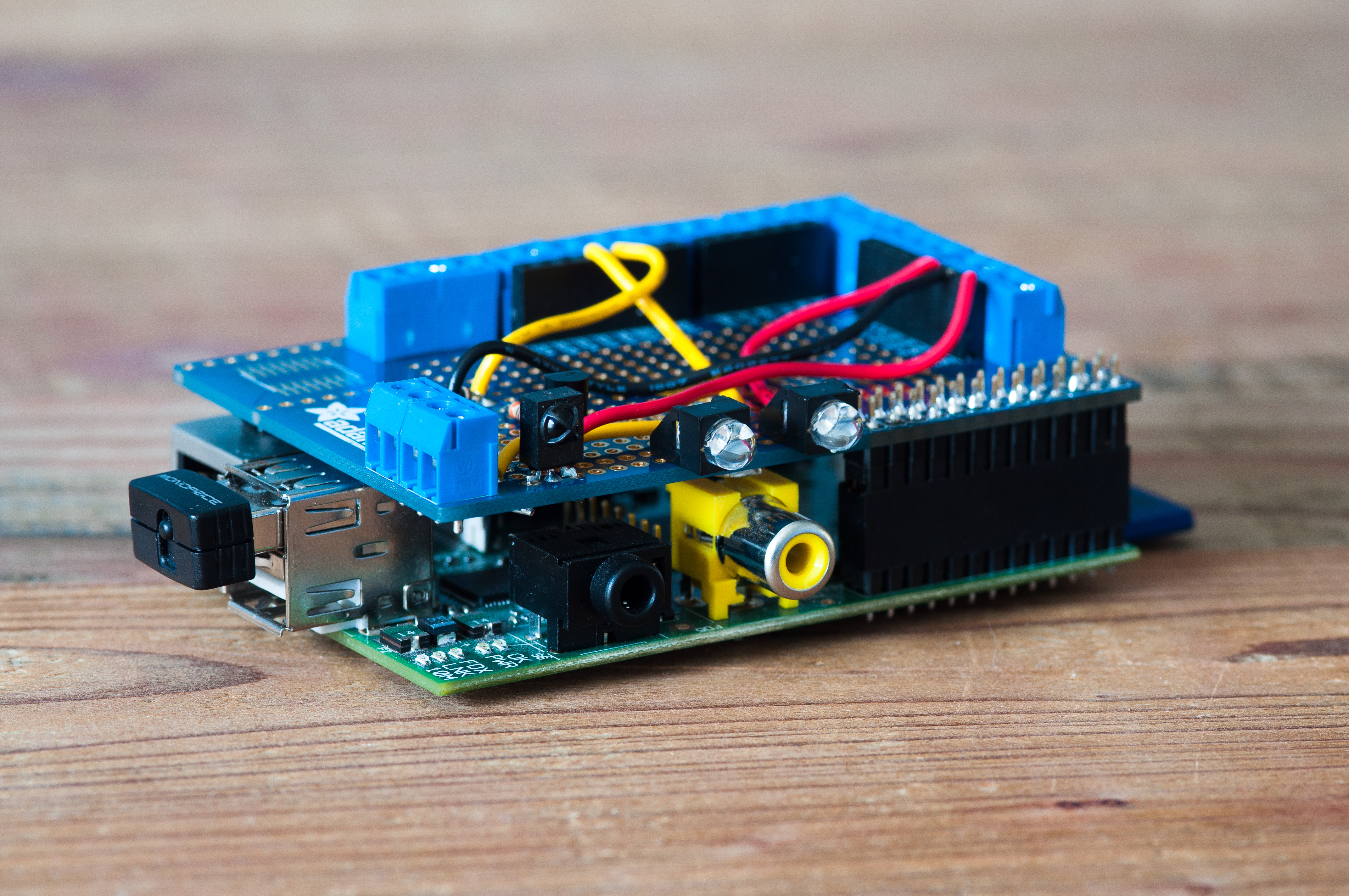
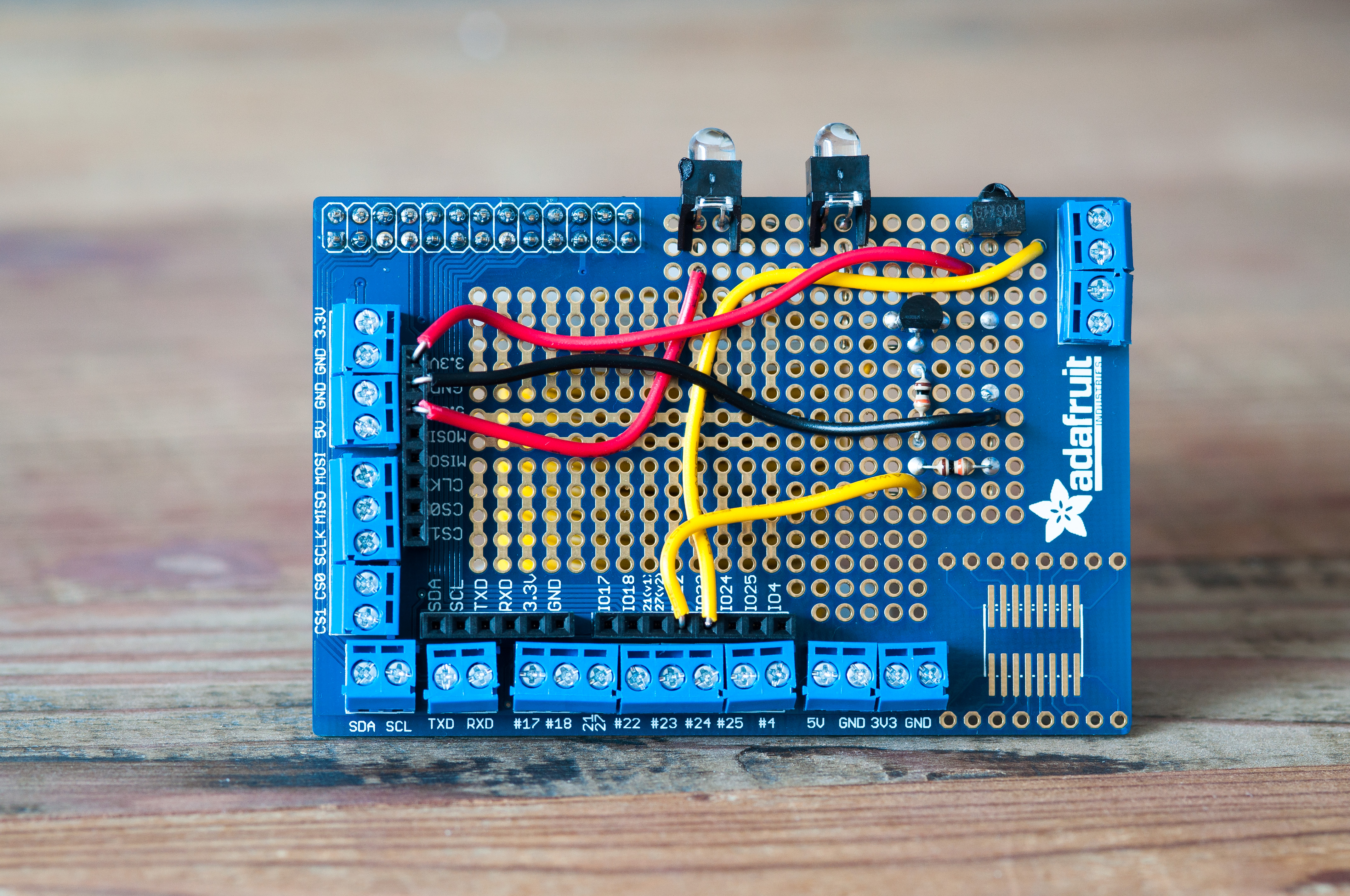
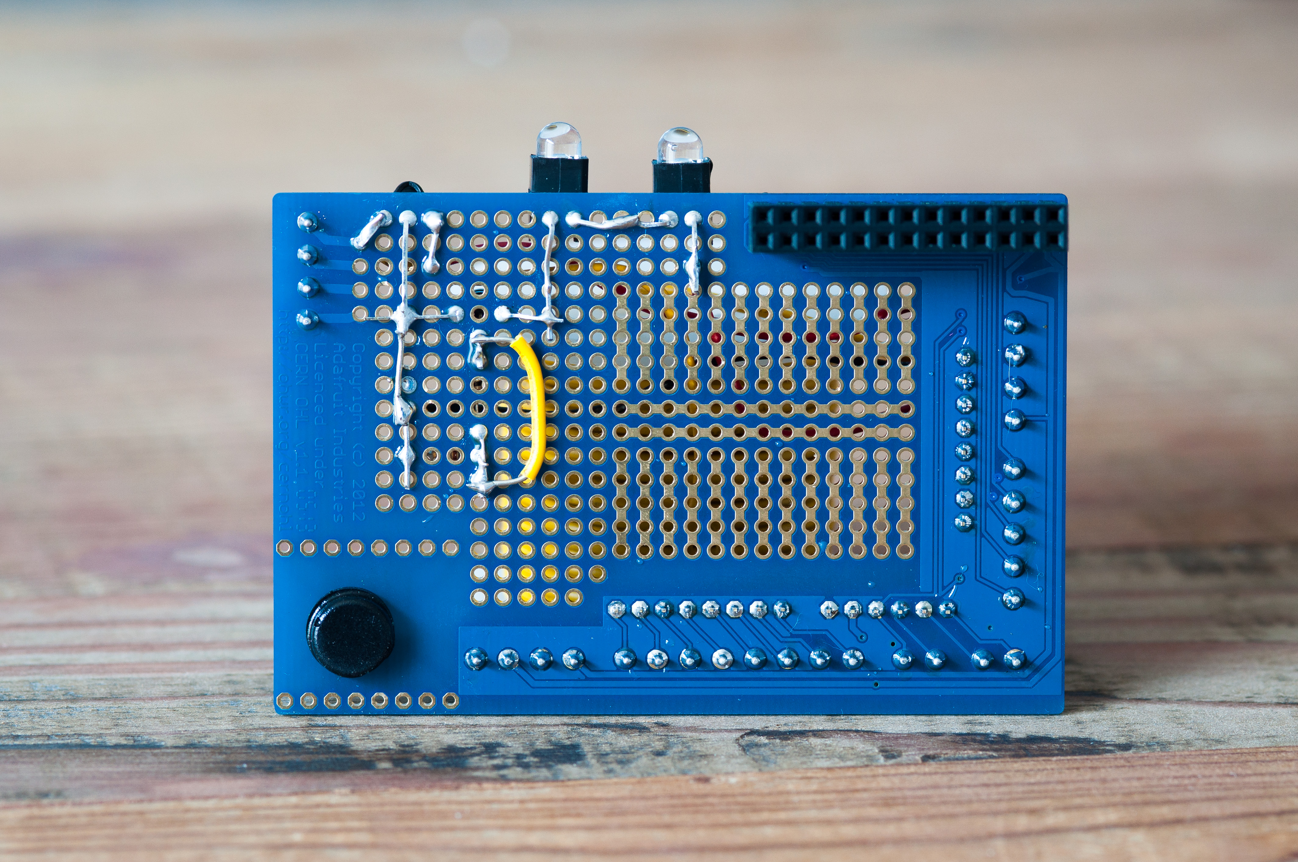
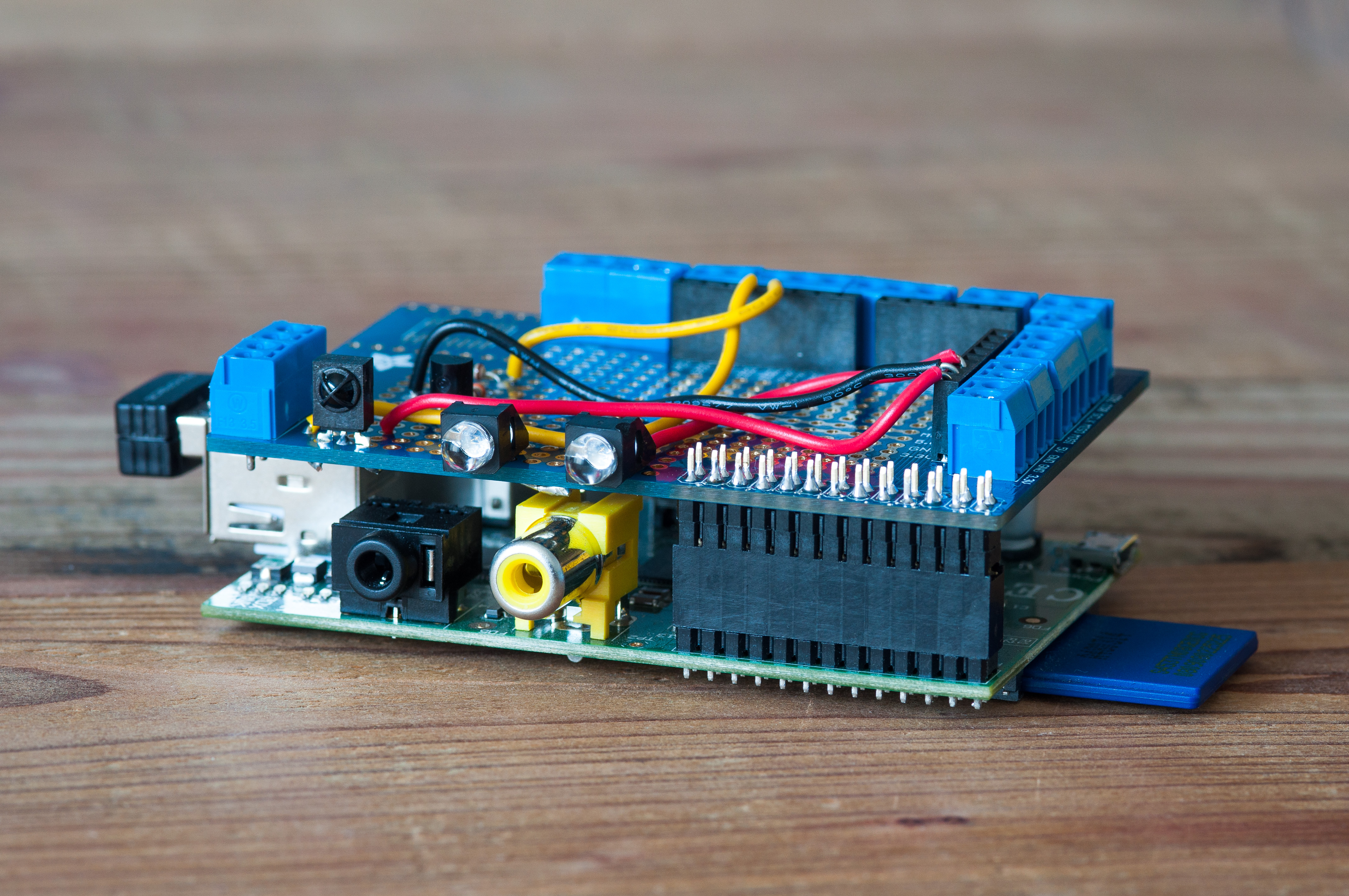
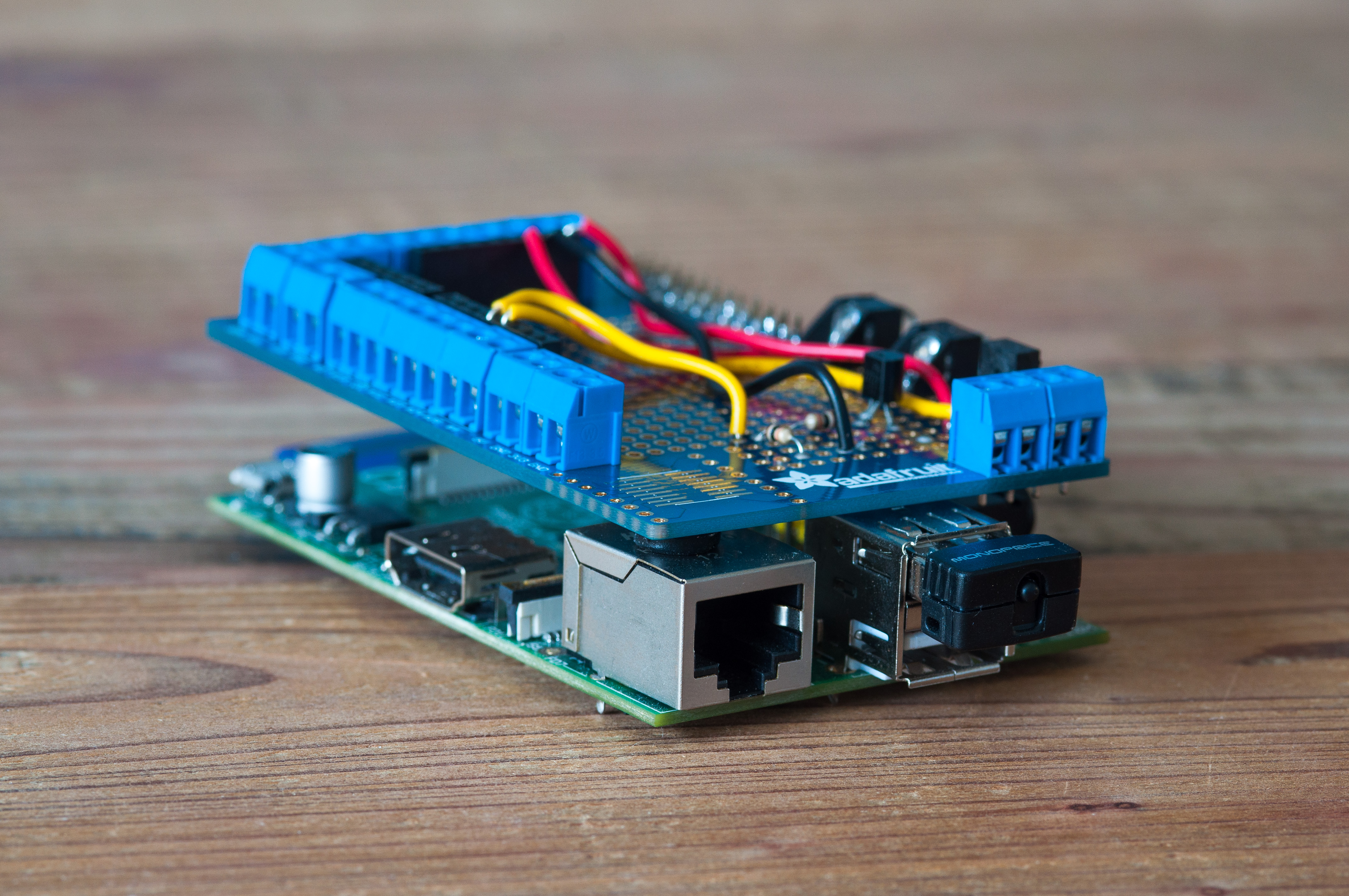
This past weekend I converted my Open Source Universal Remote breadboard layout into a more permanent soldered circuit. I used the Adafruit Protoboard as a base instead of having a custom circuit board printed, which worked out well. The protoboard is perfectly sized for the RaspberryPi and I highly recommend it for any RaspberryPi related hardware projects.
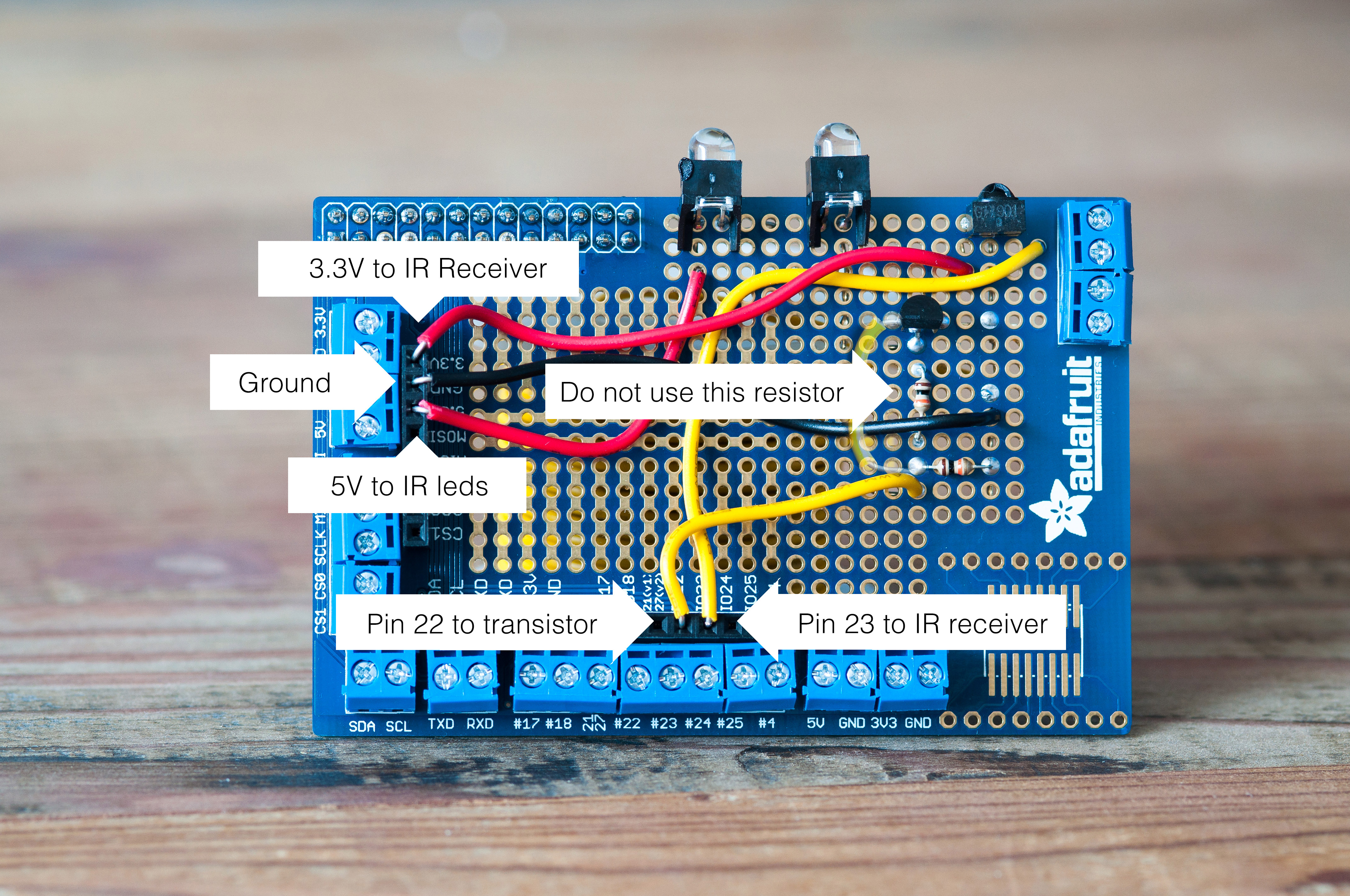
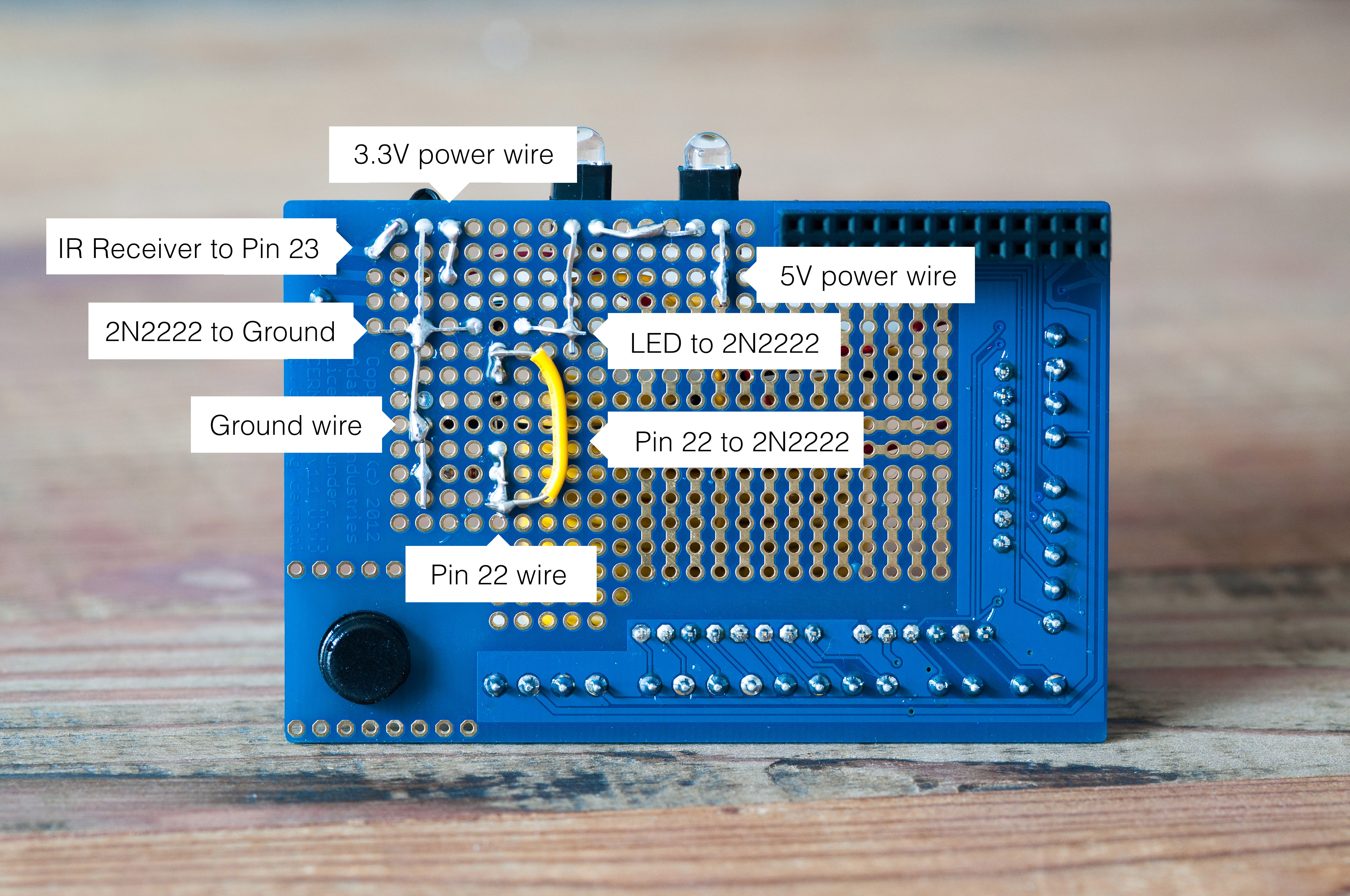
Below, I’ve attached some high resolution photographs of the finished protoboard (front and back). I’ve also created separate versions of the photographs which are fully annotated and explain how all of the components are laid out. Please note that I did make one miscalculation in my circuit which I have corrected with a yellow jumper wire. I’ve pointed out the miscalculation on both annotated photographs.
All pictures link to a full resolution image (10+ megapixel) which provides plenty of additional resolution for examining the circuit. The annotated photographs should help fill in anything that is unclear. If you have any questions, please leave them in the comments.
If you’d like to read more about this project, here is some further reading:
I frequently need to jump from the terminal to Finder in OSX. Turns out there is a very easy way to do that, which I thought I’d log here in case anyone else is searching for how to do this.
To open the current working directory in Finder, just run:
This post will serve as a guide to using a RaspberryPi, a Pebble Watch, and an Android phone (Google Nexus 4) to control your home theater from your wrist. The result is something like this:
Introduction
For a bit of backstory, around eighteen months ago I decided to start experimenting with and teaching myself electronics. I started working with an Arduino Uno and eventually moved to a RasperryPi. I wanted to build open hardware, open source, web connected devices and these seemed like the right tools for the job. I wanted to ensure that every device I built could, down the road, be controlled in entirely new ways with novel human computer interfaces like the Pebble Watch, Thalmic Labs Myo, Emotiv EPOC EEG Headset, Leap Motion, Google Glass, and others.
So, after some consideration, I chose to build a RaspberryPi powered device that controls all of the infrared devices in my home. This project has turned into the Open Source Universal Remote, an open hardware/open source device you can make yourself with a RaspberryPi and $10 of electronic parts. This post will discuss how I wired up my Pebble Watch to control my Open Source Universal remote using my Android phone.
Let’s get started!
Outline
Part 0: How it Works
Part 1: Open Source Universal Remote
Part 2: The Android Phone
Part 3: The Pebble Watch
Part 4: Conclusion / What’s next
Part 0: How it Works
At a high level, the project works like this:
User taps button on Pebble Watch.
Pebble Watch tells Android phone that a button has been tapped.
Android phone makes web request to Open Source Universal Remote API.
Open Source Universal Remote receives web request and sends out infrared pulses.
Home theater device detects infrared pulses and responds accordingly.
I’ll work backwards from the Open Source Universal Remote to the Pebble Watch.
Part 1: Open Source Universal Remote
The foundation of this project is the Open Source Universal Remote. I won’t be going into detail about how to make one here, but if you’re interested in learning more or making your own, here is all the information you need:
Open Source Universal Remote - The open source universal remote home page. This is an overview of the project and how it works.
RaspberryPi QuickStart - A guide I wrote to purchasing and doing the initial configuration on a RaspberryPi.
For this project, I’ll be using the HTTP based API that the Open Source Universal Remote generates based on the remotes and commands you teach it. Here are the three URLs I used for this project:
You could get clever and use the hostname of the open source remote, I’m just using the static IP address here.
Part 2: The Android Phone
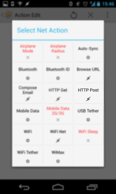
The second component of this project is an Android phone with the Tasker app installed on it. Tasker is a great app that provides a rich way to control your Android phone. One of the functions is the ability to send HTTP POST requests to specific URLs, which is the feature we’ll be using for this project.
Within the Tasker app you’ll need to create three new tasks, one for each button on the Pebble watch. Each task should be created with a descriptive name (like “Yamaha Power”) and will contain a single HTTP POST action (found in the Net menu), which will be sent to the open source remote. Here’s where the HTTP POST action can be found:
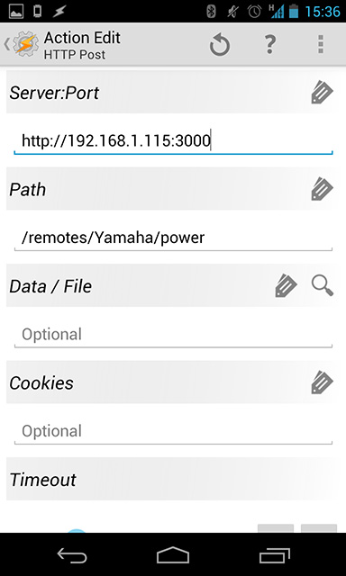
The HTTP POST action should be setup like this:
# IP / Port of the Open Source Universal Remote
Server:Port   http://192.168.1.115:3000

# Path to the remote/command combo you want to call
Path          /remotes/Yamaha/power
Once you’ve created those three Tasks, you’re ready to setup the Pebble Watch.
Part 3: Pebble Watch
The Pebble Watch was a successful Kickstarter project that launched in 2012. It’s a smart watch which connects to your cell phone via Bluetooth. It has a software development kit enabling anyone to write apps for the watch. I participated in the Kickstarter project, and have been very excited to start using my watch as a “remote control for reality.”
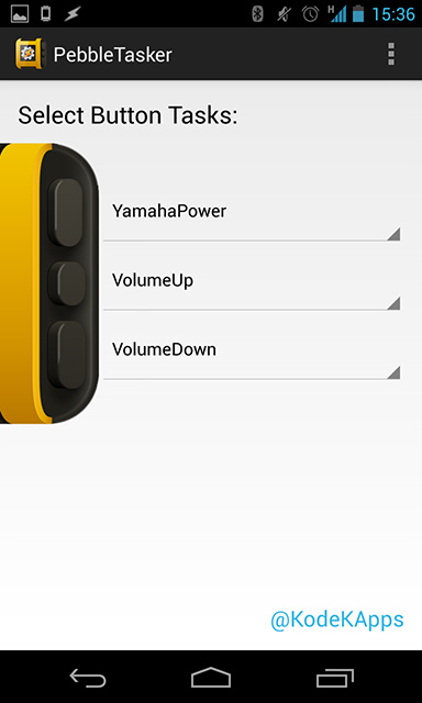
For this project we’ll be using the Android/Pebble combo app called PebbleTasker. This is a very straightforward app. You install the app on your phone, which gives you the option to install the PebbleTasker app on the watch.
Once the watch app has been installed, you use the Android app to define which Tasker actions should be assigned to which button. Select the three Tasker actions that you created above and you should be set!
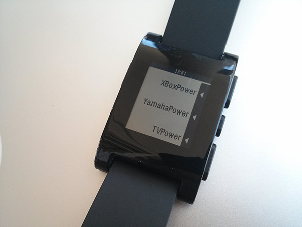
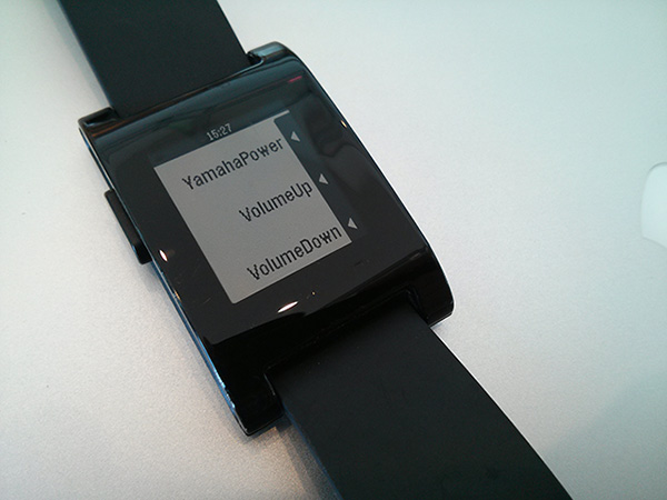
Here’s a photograph of my Pebble Watch with the above Tasker actions programmed into the watch:
Part 4: Conclusion / What’s Next
Not to wax too philosophical, but I believe that next generation user interface devices like the Pebble Watch have the potential to transform how humans interact with the digital world. The cell phone was revolutionary - it enabled humans to interact with their data while away from a desktop or laptop computer. Now, devices like the Pebble Watch and the RaspberryPi allow you to move beyond the phone and begin interacting with the digital world in an entirely new way.
As additional web connected devices are made that control lights, garage doors, cars, appliances, and beyond, the interplay between those devices and user interface devices like the Pebble Watch, Myo, Emotiv EPOC, Google Glass, and others are going to give us new and powerful interactions to control the digital and physical world. These interactions were, until now, the stuff of science fiction. These are exciting times we live in.
If you found this post interesting, please subscribe to the RSS feed to receive future updates or share this post with your social network. If you have any questions, feel free to leave a comment or send me an email (alex[at]thisdomain).
Tune in next time where I’ll be writing up how to control the Open Source Universal Remote with your mind using an Emotiv EPOC EEG headset.